• Welcome to the Checkmate Community Forums forums.

    You are currently viewing our boards as a guest which gives you limited access to view most discussions, articles and access to our other FREE features.
    By joining our free community you will be able to:

    » Interact with over 10,000 Checkmate Fanatics from around the world!
    » Post topics and messages
    » Post and view photos
    » Communicate privately with other members
    » Access our extensive gallery of old Checkmate brochures located in our Media Gallery
    » Browse the various pictures in our Checkmate photo gallery

    Registration is fast, simple and absolutely free so please, join our community today!

    If you have any problems with the registration process or your account login, please contact support by clicking here or by using the"contact us" link at the bottom of the page.

1970 Checkmate MX-14

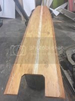
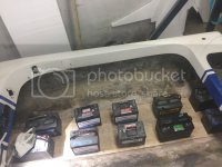
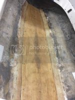
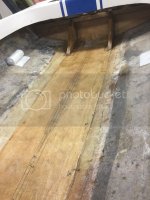
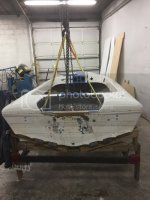
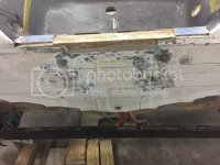
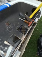
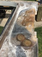
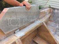
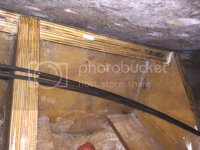
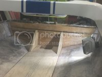
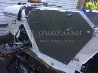
The floor was next, a ¾” sheet sealed on the bottom & edges before going in. That was screwed down with 2 sheets of glass between it and the stringer. Then a large sheet went on next overlapping to the hull. I put the knee braces in at the same time with glass between it and the floor & transom. They are made of 2 ¾” pieces put together just like the transom. Those were tabbed into the floor & transom on both sides as well.

CD33F548-260F-4BF8-8698-D133810860F9_zpsqbucgv6i.jpg

30534754-A3D1-44DC-BB68-850D797A2DF0_zpsc5srnork.jpg

47E72E50-3342-4AA5-97BF-F556F3245074_zpsohr7oqez.jpg

655B9075-C36F-4018-9233-313286AF0704_zpssd4uxuga.jpg

86D545DC-3615-40AE-A640-985B588BF055_zpsxfspzywp.jpg
 
So this is where I’m at now. Letting it dry overnight & will bring home tomorrow to cover up. Will need to clean up a few areas on the floor with air pockets & add some overlapping strips on the floor. Quite a bit of work left in the splashwell area too.

B5D8137C-8580-4119-8234-9090EDE1D799_zpsmto6req9.jpg

65647A1B-D0F0-400C-B14E-FE5DBC12D5AF_zpsufmoclr3.jpg

D049AB5D-BC01-4527-AB49-23DDC3A40D08_zpsaztbqgv9.jpg

E034ECCF-2611-45B8-9A11-3A3431D7EA6F_zpsku15hsnh.jpg

But I have to say I owe my boss a big thank you. I learn something new every day working there, and to bring my boat in there and work on it was the perfect way to get this work done. I was not set up properly at home to do this, and it was great having a whole marina of tools & materials. He was a huge help, especially with the fiberglass work. I only did a few pieces over the summer so it was great to have his help, and he answered every question I had along the way. After helping me with the first bit of glassing I was able to get the rest done myself, except for the transom install, as that took both of us. It's not the prettiest looking in some areas, but I'm very pleased that I was able to do it, and learned a lot along the way. Feels great to have a solid hull as well!


http://s1328.photobucket.com/user/remreid12/library/1970 Checkmate MX-14?sort=2&page=7 (plenty more pictures here)
 
Last edited:
Welp, been a couple of months, have you made any progress, last I saw looked like you were about to tackle the splash well, pictures of the floor sure looked familiar. I just about have my floor glassed in, working on the knees and battery tray now, bout ready to start putting what looks to be a million rivets in, good luck, mark
 
Nope, been on campus and unable to work on it. Final exams are next week so I'll be back home after that. Spring break weather wasn't very conducive, but I did manage to pick up a 1970 long shaft 1350 Merc during that week. The guy said the 135hp was too much for his boat, so he was looking to downsize. I asked if he'd take one of my 100hp's in trade. He just asked for a set of controls for the price difference. I figured I'd better jump on it, can't be too many people willing to trade a 135 for a 100. It needs wiring and fuel hoses, but it has 145psi even across all 6, so I'm very happy with it. The powerhead should drop right on my BP mid. I'll basically have a replica 1250 Super BP, minus the lower unit and louvered cowling, as a 1250 Super BP was a prototype 1350 powerhead (direct charge), just with the 1250 style bolt on starter mount, rather than the cast clamp style the 1350 has.
 
Ok so finally an update. I decided to basically do a test fit of everything by finishing 90% of the glass work (aesthetics left) and putting the whole boat together. That way if/when I need to move things around and drill new holes (more importantly fill in holes) I can do that with it not perfectly painted.

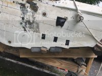
I'm making progress, slowly but surely. Seem to keep running into little things here and there that end up taking a whole lot longer than it should. A great example would be the splashwell. Between the cut out the previous owner had in the transom to lower the motor, the holes for the T-handle clamps, and the big rigging holes, there was a lot to fill in. It's by no means finished, but they have all been filled in. I have the splashwell fitting well to the transom. It will take a decent amount of body work to get things smooth for paint.

Checkmate_splashwell_holes_zpsfdnehil0.jpg

39A6625E-22A8-4A54-B5C8-A0202D56CAB8_zpsekaxrcqw.jpg

261A7489-C9C1-479D-BBBE-27373AD5FE55_zpslpex1m5z.jpg
 
Another hurdle was the trim tab mounting. I drilled the holes after making absolutely certain I had the dimensions correct. But when I bolted it on to see how it sat I noticed a large gap on the outer corners. There is a slight angle in the transom a couple inches above the bottom edge. I was afraid of cracking that trim tab plate and sealing it properly, so I talked to Sammie and we figured out the best solution. Basically a fiberglass spacer/adapter that sits flush between the trim tab and the transom. I glassed 7 sheets together, then grinded it to fit as best I could. I then used some duraglass to fill in any large voids that might still be left. I'm very pleased with how it turned out. I still need to adjust tabs to the correct angle. I'm hoping to loosen up the turnbuckles, as I like the look of these more than any new ones.

5150C7B3-8FFD-46D7-844A-E3ED9945FFFB_zpsup0djo3n.png

9B89D44E-9321-46A5-B0E1-AC74F1A4E18E_zpsblxzztae.jpg

C2F69864-545C-4149-92A1-390FE63C2480_zpsj1icolgk.jpg

662CBA35-EF51-4A3B-9C82-6BB4C87EEAD6_zps7kehq35b.jpg

6E282CBE-B9E7-4357-84D6-CA79833FF7A2_zpscq2mxz7s.jpg

C9BBCBD0-E3D3-4467-AFC7-8099B1348872_zpsizwjfkpw.jpg

This bar stock shows where the angle in the transom is, going right through where the trim tabs mount.

56873F59-0676-41D7-859D-AF9746186218_zps2v9bzgc3.jpg


5855430C-1D5E-427D-82B6-2E7251C68429_zpstqhzfpde.jpg

Wax paper works so well

714AEE76-835C-4E26-96C8-1A299EC0EA38_zpsfqblbvgp.jpg

984B367B-BE3A-4E82-BD5D-C31AEFF7EBC1_zpsskiuh6jd.jpg

889EB2EB-B768-4CF5-B7D5-F3AF699BA296_zpsghmgooit.jpg

Just realized I don't have close up pictures of them finally mounted
 
Probably my biggest concern was that of the transom bracket. With this 19" transom, the proper running height of a short 15" engine is at 3.5" higher (as per Sammie's advice). At this height, the T-handle clamps are no longer in line with the transom, as they are too high. Because of this, the transom bracket needs to be designed very well. Sammie and I came up with a very good design. It uses 7075 0.25" T651 Aluminum plate going down the splashwell and transom. Then there's a welded 6061 rectangular tube stock piece in between, and bolted together. Unfortunately, after drilling a few holes and test mounting it, I discovered my very important 3.5" tall measurement was not seen in the 5 page engineering drawing packet I gave the welding shop, so they need to cut down the 3.9" (still have no idea where the 3.9" comes from) height down to 3.5". But with the measurement issue aside, I was very pleased with how it turned out.
F17052A6-AE88-4B4E-B649-B0F9761B716D_zpspru8xxlb.jpg

417950FD-9592-49D5-B7A2-3263B20B0B77_zpsnx7thb82.jpg

335C493C-B86C-459E-9A5A-4ED73208A71E_zpshzhjr5xs.jpg

1100983C-6051-4602-9170-1A672A89843A_zpsia6tic3p.jpg

DCBA1AD6-F672-4B2F-BF29-2425AAD3ECDE_zpsw0xazf1m.jpg
 
:thumb: So with the 3.5 raise, where does the prop shaft end up, will it be even with the bottom or above it???? And you have a 15 inch mid???
 
Prop shaft will be below the pad. They finished fixing the transom plate yesterday so today or tomorrow I should have it mocked up again and can take a picture of it. And yes it's a 15" short shaft.
 
:devil: Just to be a dick, how much difference would 3/8 of an inch make, you must really be an engineer, 5 page blueprint???:poke: I made something similar to that for my first MX-15 out of scraps at work, mounted it up on the transom and went to drill the mounting holes and a regular drill wouldn't touch it, turns out it was inconel for making airplane motor parts, had to get solid carbide drills from work to make any kind of hole in it, tough stuff
 
Last edited:
3/8" would be a question for Sammie. He said 3.5" above a 19" transom so that's what I'm doing. Eventually too high will result in lack of water pressure and cooked powerheads. Four pages are for 4 parts with multi views and isometric views, and the 5th has the exploded view of the assembly. I have a dual opposed rack and pinion ride guide steering system for this. That gold tube attached to the tilt tube is for the second cable. I filled in all the holes in the splashwell for the cables because I will be drilling new ones in as high as I can to make the cables in line as much as possible. I'm hoping to avoid the toploaders. I don't like the look of them.

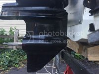
Here's where the lower sits now. I still need to grind a radius in the transom plate for curvature of the turnbuckle bracket. So it will drop another 1/4" or so.

806D5C6C-4407-4222-81D8-54949F5E8908_zpskl1hk76g.jpg
 
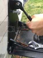
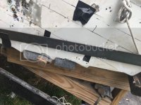
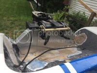
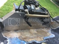
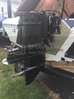
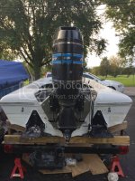
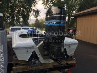
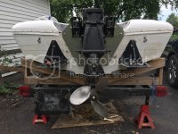
Ok I've been bad with updates. Trim tabs have been mounted and sealed. I riveted the deck and hull back together after all the remaining glass work was finished. Most of the work was in the spashwell area of the transom, getting the deck and hull to fit well with the new transom. Transom plate was then mounted and sealed. I spent a long time measuring and remeasuring to make certain I have the centerline correct on the hull based on the pad. Once I had that marked I mounted the mid and lower. There are two bolts in each trim bracket, at the upper and lower extremes, and 2 more bolts in the bottom of the clamp bracket that go through the transom and the crossmember. So in total, 6 bolts through the motor, 4 of which go through the wood transom. I feel very confident in the structural integrity of this setup. I actually stood up on top of the mid section and jumped around a little. Absolutely no movement in the transom or transom plate.


EC2687B7-3E60-4D3A-831C-E57CE579B2F6_zpsndbehr9j.jpg
The 4 bolts through the trim brackets

55F2EF54-145B-44CE-BA3C-B696586730EB_zpszqpvzpjj.jpg

9ED3F746-CC77-4532-8A6B-327FB3C9034A_zpsoi4rwla2.jpg

F0E65F77-36DF-4D5C-852C-D4E0F2A88CD0_zpsdvomwdki.jpg
The bolts coming through the cross member. Had to buy 8" bolts.

None of the bolts are sealed at this point in the pictures. Used a lot of 5200.
 
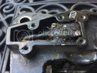
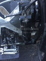
Next issue was the power trim. I went to mount the rams and they wouldn't line up properly. Turns out the BP mid is wider than the regular mids. So for now I will just flip the lower mount 180 degrees and put a spacer in. I could cut down the cylinder on the ram at a a later date. Otherwise, I worked on the power trim limit switch. Local marina actually had a new sensor in stock. Then I put a new spring in the button, and replaced the gasket (made my own). I got the steering greased and mounted properly. Turns with one finger. I could use new linkage arms, as the one is bent and limits the range that I can adjust.

3B85BC76-74E5-4CA5-9D05-20E97546E9A9_zpss6xja6g4.jpg

ED989520-2868-4647-A07F-DB7D40A49EAF_zpsyeugfd94.jpg

6AB7FA1A-DB8D-4B57-8F8E-6BEE4DE4C456_zps179nvn3i.jpg

9825B23B-8A01-44A2-944A-F5AF6D865ADC_zpsmhyn7iri.jpg
 
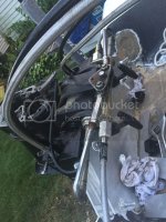
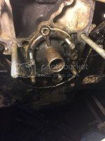
So I had the motor together earlier this summer to test fit everything and make sure it would fire up. I then pulled the powerhead so it would be easier to just mount the mid & lower on when lining it up with the center of the pad. While I had the powerhead off, I decided to replace the lower crankcase seals. I had never done this before, but it wasn't too bad. Just took a little bit to get the cover off that the seals mount into. I also rebuilt the fuel pumps while the powerhead was off. At that point the powerhead was ready to go. Mounted it back on and put the louvered cowling on it.


AA72DB50-52F8-4C1B-9CF0-7C4E05F8F4E1_zpskrld5r6l.jpg
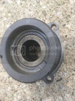
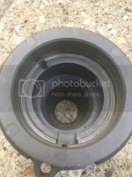
This is the lower crank case cover. Holds the seals and the bearing in place.

91E4A1C7-9547-4EB4-AAA0-C1C22D78870E_zpsq3m8bzoq.jpg
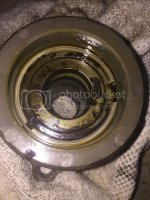
Here are the old seals (looking down into the cover).

95CDC087-31C2-4661-87F3-9224D294BF12_zpsw8c0ghoj.jpg

FB21B2E2-FB38-4A0C-96D2-1F98C63C969F_zpsw6cn1tsv.jpg
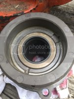
Here is the cover with the old seals removed.

6EBC15EF-6BC7-45F5-8E8F-FD9685D9F91A_zps8khnwhnk.jpg
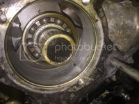
This is what the bottom of the motor looks like with the cover off.

7DEFA79D-E445-457E-8022-090C17556C55_zpswbwfvcwb.jpg
Here is the cover with the new seals in.

D2C2A232-F610-44D7-9E6F-4FA97179CFC1_zpsclq1xvxa.jpg

76CAF7CA-4AB9-40C5-B085-1FECB55F4DA2_zpsmkar24yc.jpg

A00E4E51-2655-41D3-91D4-D1064788A2E9_zpsb2seoic5.jpg
 
Relly nice work

You are doing a really nice job on your Checkmate. Wish I could of been there to Help you in Person. Take Care and remember I am always here to Help you. Sincerely Sammie from Action Marine
 
:thumb: She's coming along, when you replaced the lower crankcase bearing and seals, did you loosen the crankcase bolts, it comes out easier, anyway, I saw on another thread you need new spark plug wires, if you are not concerned with originality, I ordered plug wires from Jegs for a small block Chevy (solid wire, 90 degree boots) and ordered the screw in ends from MarineEngine.com and made my own. Looking good, good luck. Plan on getting her wet this year???
 
I didn't know about the lower crankcase bolt trick. I screwed some bolts into the those tapped holes on the cover and worked it out with those. Probably took longer that way but it came off eventually. As for the distributor wires, I was referring to the small 3 (white, black, brown) wires. Mine are quite rotten. SCT had them replaced by Wayne Canino. I hadn't heard of his distributor wire replacement before and I had thought they were not replaceable. I would like to pull the top of the engine apart and replace the upper crankcase seals. At that time I think it would be good to send the stator and distributor to Wayne to get new wires. I'm not too concerned about the spark plug wires. From what I've seen online they last a very long time as long as the ends don't break off.
 
Ok, who is this Wayne Canino and what services does he offer, is he on this forum, or Mercury forum, do you have a address and number for him, I could use some wiring myself, thanks, Mark
 
Back
Top